Understanding Dust Explosions (and Determining Combustibility)
Claim
Dust explosions are a common hazard in many industrial environments where dispersed powder or other types of combustible materials are present within a confined space. Understanding dust explosions is a key step when creating better health and safety practices at your plant to prevent a serious accident from occurring.
DUST EXPLOSION TERMINOLOGY
In order to understand dust explosion risks, it's important to familiarize yourself with the terminology used. Below is a list of several key terms* used by many manufacturers and experts:
- Minimum Exposible Concentration (MEC): The minimum concentration of combustible dust suspended in air, measured in mass per unit volume, that will support a deflagration.
- Minimum Ignition Energy (MIE): The lowest capacitive spark energy capable of igniting the most ignition-sensitive concentration of a flammable vapor–air mixture or a combustible dust–air mixture as determined by a standard test procedure.
- Kst: Rate of pressure rise for suspended combustible dusts. An index is used to categorize dusts with certain Kst values.
| Dust Classification | Kst |
| ST-1 | 0 to 200 |
| ST-2 | 201 to 300 |
| ST-3 | 301+ |
- Pmax: Maximum pressure created by a deflagration of suspended combustible dusts.
- Limiting Oxygen Concentration (LOC): The amount (%) of oxygen required by a suspended combustible dust to support a deflagration.
Each of these product characteristics helps manufacturers like us to understand how best to design systems to prevent a deflagration or explosion.

DETERMINING IF YOUR MATERIAL IS COMBUSTIBLE
Upon learning and understanding these terms, it’s important to know whether your material is classified as a combustible dust. There are a few ways to determine this. You can:
- Confer with the manufacturer/supplier
- Check online resources (NFPA Standards)
- Send a sample of your product to a testing center. Most testing centers will be able to provide you with all of the information above. As part of ASTM E1226, these test centers will perform a “Go/No-go” screening test to determine whether or not your product would be classified as a combustible dust. If determined that your product is not a combustible dust, the owner/operator of the process shall maintain documentation demonstrating the dusts are not combustible or explosible. (NFPA 652). If determined that your product is a combustible dust, the next step would be to perform a Dust Hazards Analysis (DHA). A DHA should only be performed by a qualified person.
A couple of other things to be aware of relating to a DHA are:
- For existing processes, with the exception of the food industry, DHAs should have been completed by September 7, 2020.
- A DHA should be reviewed and updated every 5 years.
- For all new processes handling combustible dusts, a DHA should be performed.
ADDRESSING DUST EXPLOSION RISKS AND HAZARDS
There are two primary methods to address explosion risks and hazards identified during the DHA: a prescriptive approach and a performance-based approach. In this post, we will be focusing specifically on the prescriptive approach.
Per NFPA 652, explosion protection systems shall incorporate one or more of the following methods of protection:
- Oxidant concentration reduction (in accordance with NFPA 69)
- Deflagration venting (in accordance with NFPA 68)
- Deflagration venting through listed flame-arresting devices (in accordance with NFPA 68)
- Deflagration pressure containment (in accordance with NFPA 69)
- Deflagration suppression system (in accordance with NFPA 69)
- Dilution with a non-combustible dust to render the mixture noncombustible
Here at De Dietrich Process Systems, we utilize the oxidant concentration method. This may be more commonly referred to as "inerting" or "inertion."
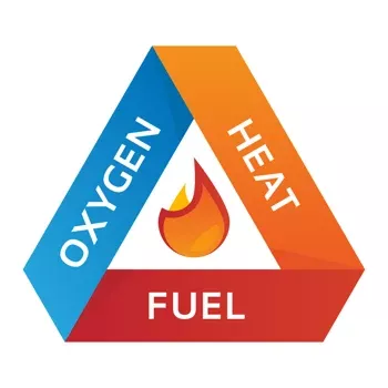
When looking at the fire triangle, we are essentially removing the oxygen side of the triangle in order to not create a combustible atmosphere. For those unfamiliar with the fire triangle, a fire requires 3 things: fuel, an ignition source, and oxygen.
DUST HAZARDS ANALYSIS (DHA)
Per NFPA 652, the qualified person who is leading or performing the DHA should be familiar with the hazards of combustible dusts. Typically, a team performs a DHA. For some processes, this team might be as little as two persons, or for larger, more complex processes it can require more. This team is comprised of a variety of persons (such as facility operators, engineers, owners, equipment manufacturers and consultants) whose background and expertise can include the following:
- Familiarity with the process
- Operations and maintenance
- Process equipment
- Safety systems
- History of operation
- The properties of the material
- Emergency procedures
When inerting a product, you are removing the oxygen and adding back an inert gas (a gas that will not support a fire) in its place. The most common gas used for this is nitrogen. However, in some cases, when nitrogen isn’t available or isn’t compatible with the process, other gases such as argon or carbon dioxide can be used.
One caution that must be taken into consideration when inerting systems is asphyxiation. It is very important that proper measures are put into place to keep the working areas safe for operators.
There are two ways to monitor the oxygen concentration within a system: continuous or non-continuous. For continuous monitoring systems, oxygen concentration must meet one of the following criteria:
- Where the limiting oxygen concentration (LOC) is greater than or equal to 5 percent, a safety margin of at least 2 volume percent below the worst credible case LOC shall be maintained.
Example: LOC = 6%, Acceptable O2 conc. = 6% - 2% = 4%
- Where the LOC is less than 5 percent, the equipment shall be operated at no more than 60 percent of the LOC.
Example: LOC = 4%, Acceptable O2 conc. = 4% x 0.60 = 2.4%
For non-continuous monitoring systems, oxygen concentration shall meet one of the following criteria:
- Where the LOC is greater than or equal to 7.5 percent, a safety margin of at least 4.5 volume percent below the worst credible case LOC shall be maintained.
Example: LOC = 8%, Acceptable O2 conc. = 8% - 4.5% = 3.5%
- Where the LOC is less than 7.5 percent, the oxygen concentration shall be designed to operate at no more than 40 percent of the LOC.
Example: LOC = 6%, Acceptable O2 conc. = 6% x 0.4 = 2.4%
In addition to continuous and non-continuous monitoring, there is one other acceptable method to ensure proper oxygen concentrations. This procedure involves pulling a partial vacuum and then breaking the vacuum with inert gas, and is permitted without measuring the oxygen concentration if all of the following conditions apply:
- The vacuum condition is held for a time to check for leakage.
- The vacuum level is monitored.
- The vacuum-creating medium is compatible with the process chemistry.
- The residual oxygen partial pressure is calculated or demonstrated by test to be at least 40 percent below the LOC.
NFPA 69 provides several guidelines for safe practice with inerting type systems. Please reference this for safe design parameters for these types of systems.
As you can see from some of the detailed procedures outlined in this post, the minimization of dust explosions is a serious topic that deserves attention. For additional questions about NFPA guidelines, please feel free to reach out to us. We would be happy to help in any way possible. For help conducting a dust hazards analysis, DDPS can answer questions as it relates to our powder handling solutions, but ultimately we recommend you request assistance from a combustible dust expert or firm.
*Each of these values can be obtained from Standards from the American Society of Testing and Materials (ASTM).
- ASTM E1515: Standard Test Method for Minimum Explosible Concentration of Combustible Dusts
- ASTM E2019: Standard Test Method for Minimum Ignition Energy of a Dust Cloud in Air
- ASTM E1226: Standard Test Method for Explosibility of Dust Clouds (determines Kst and Pmax)
- ASTM E2079: Standard Test Method for Limiting Oxygen (Oxidant) Concentration in Gases and Vapors