Explosion protection

1. Requirements for the operation of processing plants in
explosive atmospheres
Operators of chemical plants are not always able to completely eliminate the risk of explosive atmospheres around the equipment.In order to operate plants in such areas that are hazardous due to explosive atmospheres, commonly also referred to as zones, the operator must take measures to eliminate all ignition sources. The relevant requirements are laid down in various Directives of the European Union that are in turn implemented in national legislation. For the approval of such plants, the manufacturer must conform to the requirements of Directive 2014/34/EC, also known as ATEX 114, or ATEX equipment directive, while the operator must meet the requirements laid down in Directive 1999/92/EC, generally referred to as ATEX 137, which concerns workplace safety.
1.1. Requirements to be met by manufacturer
The plant must be designed and manufactured according to the directive 2001/95/EC on general product safety. Based on the ATEX zones inside and outside the plant defined by the operator, the manufacturer must take measures to ensure that all equipment conforms to ATEX 114. Compliance must be documented in the plant documentation. The plant does, however, not bear the CE mark, as, according to the ATEX 114 guideline, it is deemed a process plant consisting of individual devices.
The individual devices of the QVF® glass plant that might be electrical or mechanical ignition sources are certified according to ATEX 114 and thus bear the CE mark.
The QVF® stirrer drives with mechanical seals, the QVF® temperature and QVF® pressure sensors are, for example, certified according to ATEX 114 in device category 1 (see table 1), device group II and explosion group II (see table 2) for the inside of the apparatus. They can thus be used in plants where the inside of the plant is classified as zone 0 according to ATEX 137. Around the plant, zone 1 or zone 2 conditions must be met, as the above devices outside the QVF® glass plant conform to device category 2.
Table 1: Device category

Table 2: Explosion groups:

1.2. Requirements to be met by operator
The plant operator must conform to the requirements of the Directive 89/391/EEC on the introduction of measures to encourage improvements in the safety and health of workers at work. To meet the requirements of ATEX 137, the operator must comply to the national implementation of the CENELEC report CLC/TR 50404:2003 "Electrostatics - Code of practice for the avoidance of hazards due to static electricity" (CLC/TR 50404). In Germany for example the national implementation is the "Technical Rules for Operating Safety" TRGS727 for the operation of plants within ATEX zones and for the prevention of ignition hazards caused by electrostatic charges (TRGS727) implement this code of practice. The concept to avoid electrostatic charges and described in the following is in line with these technical rules and hence in line with the european code of practice CLC/TR 50404.
The manufacturer prepares the devices to be safe for use in the ATEX zones specified by the operator, and provides the necessary equipment documentation for the explosion safety documentation. This ensures that the operator is able to comply with Directive 89/391/EEC so that the safe operation of the QVF® plant can be realised and properly documented.
2. Sources of electrostatic hazards in process plants
Electrostatic charges in process equipment are normally the result of frictional electricity generated when two different materials are brought into contact and then separated, e.g. when rubbed against each other. One material becomes positively charged, while the other becomes negatively charged. This happens, for example, when a fluid medium flows through a pipe. When these charges reach a certain level, electric discharge might take place by sparking. This is, of course, particularly dangerous in an explosive atmosphere, which could ignite. It is therefore important that electrostatic charging does not take place in such hazardous areas. Table 3 shows examples of processes that may lead to electrostatic charges. In all cases, it is the responsibility of the operator of the equipment to carry out a risk assessment. The level of the charging depends on the electric conductivity of the fluid. Normally, dangerous electrostatic charges only occur with fluids whose conductivity is low. Charging can thus often be prevented by adding suitable additives such as salts to the fluid since they increase the electric conductivity of the fluid. Often, only minute quantities (i.e. concentrations in ppm range) are sufficient to effectively eliminate the risk of electrostatic charges.
Table 3: - Examples of processes generating charges

In addition, there are processes that are generally classified as highly charge-generating – see table 4. Wherever possible, such processes should be avoided or at least minimized, in combination with special safety precautions.
Table 4: Examples of processes generating high charges

3. Protective measures for the prevention of electrostatic ignition in
process plants
If electrostatic charges are generated by frictional electricity, consequential electrostatic charges in equipment that is remote from the actual friction point might be caused by electrostatic influence. The charges occurring at the point of friction as well as those due to influence can be eliminated by earthing conductive materials and avoiding the use of non-conductive materials. The necessity and level of such measures depend on the likelihood of charging processes occurring in and around the equipment.
The protective measures outlined below conform to CLC/TR 50404 and TRGS727 are designed to prevent electrostatic ignition under specific operating conditions.
Such measures are, however, only required, if the equipment is not protected by an inert atmosphere or if there is a risk that an explosive atmosphere is around the equipment.
3.1. Potential equalization
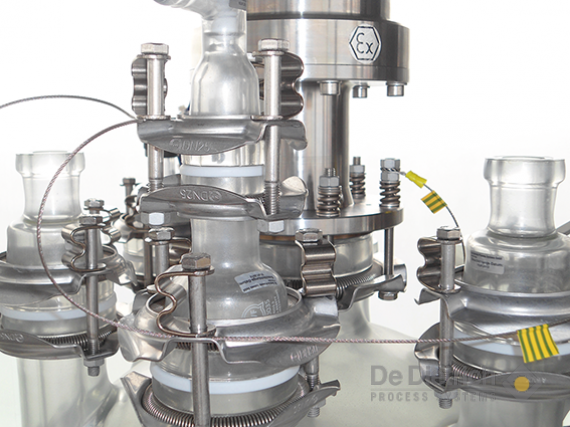
If electrically conductive components are earthed or dissipative components are connected to the earth electrostatic charges cannot occur and there is thus no risk of electrostatic ignition. In order to meet the relevant CLC/TR 50404 requirements, it is sufficient to cater for currents of up to 10-4 A. For such low currents, even poorly conducting earth conductors with a relatively high resistance of 106ΩB tend to be adequate. Earthing according to CLC/TR 50404 must, however, not be confused with earthing of electrical devices, as this requires proper conduction of much higher currents to activate overload fuses. In this document, the term "potential equalization" is used to describe "earthing according to CLC/TR 50404". Potential equalization can be achieved by connecting each individual component to the earth, or by connecting conductive components to each other and providing a single shared earthing conductor. The potential equalization cable must be clearly identifiable (yellow/green plastic cover, see figure 1, page 5).
3.2. Avoidance of non-conductive materials
Non-conductive materials can become highly charged during certain processes. Due to their insulating properties, it is not possible to discharge these parts by means of potential equalization. To eliminate the risk of electrostatic ignition, non-conductive materials are replaced by conductive or dissipative materials. Alternatively, they can be coated with a conductive of dissipative material. Dangerous electrostatic charging can be prevented by ensuring proper potential equalization of the conductive or dissipative surfaces. Borosilicate glass 3.3 is hydrophylic and its surface normally disspative - see section 3.5.2.1.
3.3. Protective measures for processes generating no charges
There is no need for potential equalization and the use of non-conductive materials is permitted, provided that there is no risk of dangerous charges at the inside and the outside of the plant, or if experiments and tests have shown that such risk can be excluded.
3.4. Protective measures for processes potentially generating high charges
If high electrostatic charges are to be expected in a process (see table 4), apparative measures must be taken in order to prevent such charges in explosive atmospheres. Irrespective of the ATEX zone, all conductive and all dissipative components and objects in the vicinity of the process must be included in the potential equalization concept. Furthermore, all non-conductive materials must be avoided and replaced either by conductive or dissipative materials, or by components with a conductive or dissipative surface coating.
3.5. Protective measures for processes potentially generating medium to low charges
If it is not possible to fully eliminate charge-generating processes, and if the processes are not classified as highly charging (see for example table 1), dangerous electrostatic charges can be prevented by taking suitable apparative measures determined by the actual ignition risk. In such cases surfaces of non-conductive materials are permitted up to a certain size and conductive or dissipative parts need only be included in the potential equalization concept, if their capacitance is above a certain limit value. The permitted size of the non-conductive surfaces and the permitted size of conductive and dissipative objects not necessarily to be connected to the potential equalization depend on the actual ATEX zone. Detailed instructions are laid down in CLC/TR 50404 and TRGS727 and their realisation described in the following sections.
3.5.1. Potential equalization in QVF® glass plants
QVF® glass plants contain conductive components such as metal flanges, etc. as shown in figure 1. These components are not in direct contact with the medium fed through the plant and might thus be electrically charged only by electrostatic influence. The charge accumulating in an object depends on its electric capacitance. The permissible capacitance, and hence size, of the conductive object without potential equalization is a function of the ATEX zone and the explosion group. For zones 2, 1IIA and 1IIB, CLC/TR 50404 and TRGS727 specify a guide value for the maximum permissible capacitance of 10pF and prescribes potential equalization for metal flanges with a nominal diameter of DN50 and bigger. For zones 0 and 1 IIC, potential equalization must be implemented for all metal flanges, irrespective of their nominal diameter.
Figure 2 illustrates the need for potential equalization of metal flange connections depending on their size, ATEX zone and the explosion group.
Fig. 1: Potential equalization of metal flanges by means of attached stainless steel cables
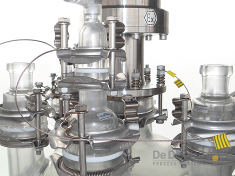
Fig. 2: Selection diagram for potential equalization of stainless steel connections
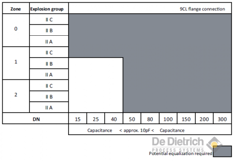
Fig. 4: Potential equalization connection
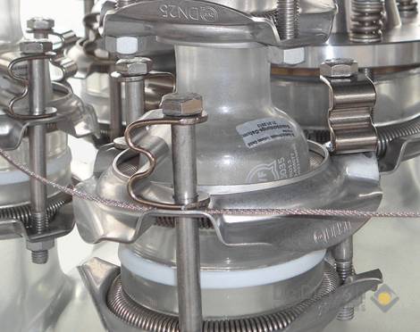
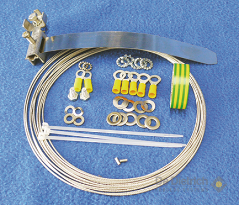
Fig. 3: The QVF® potential equalization kit contains all components that are generally required for the installation of a potential equalization concept in a glass plant.
Given the large number of metal flange connections in glass plants, the QVF® SUPRA flange connections (figures 4 and 5) have specifically been designed for easy installation and reliable potential equalization. The stainless steel flanges are only connected to each other after installation (figure 5). For this purpose, a 1.5 mm thick stainless steel cable is attached to each flange by simply turning the preloaded spring (item 1 in figure 5), so that an electrically conductive clamping connection is established with the stainless steel flange ring (item 2 in figure 5). This clamping mechanism is corrosion-proof and can only be opened with a tool. As this potential equalization line has also a resistance of less than 106Ω, it conforms to the requirements set out in CLC/TR 50404. The steel cable connecting all components is then connected at a suitable point to an earth conductor. The QVF® SUPRA-Line system has the added advantage that only one continuous steel cable is required to ensure proper potential equalization. Should the cable become disconnected from one of the flanges, the other metal flanges remain safely earthed.
QVF® glass plants normally also contain other conductive components such as flanges at bellows, valves, stirrers, sensors, holders and frames, which are all equipped with connecting points for potential equalization. Charges inside of the glass system are taken out by dissipative media themselves and along the inner dissipative glass surface through the e.g. above mentioned dissipative PTFE-components if connected to a potiential equalization.Within glass piping the dissipative angular PTFE-gasket is the universal solution for this connection as it can be placed at almost any location where necessary.
Fig. 5: QVF® SUPRA flange connection
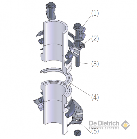
(1) Clamping element
(2) Deep-drawn stainless steel ring (1.4301) with earthing groove
(3) Silicone ring or SECTRANS coating prevents direct pressure of the stainless steel component on the glass
(4) PTFE universal gasket
(5) Temperature-resistant component made in stainless steel (1.4310)
3.5.2. Avoidance of non-conductive surfaces in QVF® glass plants
In glass plants, non-conductive surfaces are normally only found on plastic parts made in PTFE or similar materials. Under certain circumstances, they might also occur at the outside of glass components. Such non-conductive surfaces are to be prevented or at least minimized.
Where PTFE or other plastic components cannot be avoided, dissipative versions of these components containing conductive pigments, or versions coated with a conductive material, might be used, so that their surfaces are no longer classified as non-conductive.
External glass surfaces can, for example, be equipped with a dissipative QVF® SECTRANS coating as described in the following section. For the inside of glass plants, TRGS 727 demands that the same measures as for dissipative equipment must be taken if medias are operated in the glass system which lead to a disspative inner glass surface. Otherwise further measures as an inertisation have to be taken.
3.5.2.1. Dissipative QVF® SECTRANS coating of QVF® glass components
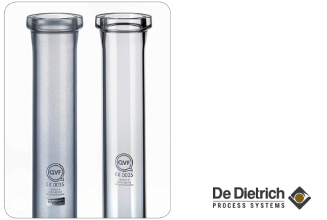
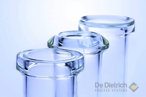
Borosilicate glass 3.3 is hydrophilic. The aqueous condensate film that is formed on its surface at a relative air humidity of, say, 50% and a temperature of 23°C reduces the surface resistance to 1011Ω. Under such conditions, glass plants cannot be electrically charged to a dangerous level by external processes, such as rubbing on the surfaceas as long as the outer surface is connected to a potential equalization. When the air humidity is below 50% and the temperature is above 50°C, there is no such film so that additional measures should be taken to prevent dangerous electrostatic charging if the glass plant is to be operated in a zone 0 or 1 IIC environment (figure 6). One option is the use of glass coated with dissipative QVF® SECTRANS (figure 7), which reduces the outer surface resistance to a value up to 108Ω. This surface resistance is measured according to DIN IEC 93 VDE 0303 T30 on each coated QVF® glass component and compliance is confirmed by a label on the component featuring the date of the measurement. Stainless steel flange rings up to DN300 are mounted without silicone rings (item 3 in figure 5, page 6) on components with dissipative coating. The dissipative coating is thus connected through the stainless steel insert (item 5 in figure 5, page 6) to the stainless steel flange ring (item 2 in figure 5, page 6) of the QVF® SUPRA-Line. This arrangement ensures that any electrostatic charge occurring on the surface is safely removed through the stainless steel cable clamped to the flange connection. For components with a nominal diameter from DN450 onwards, the surface potential is equalized through the stainless steel flange connection of a glass side neck with a smaller nominal diameter, or through an additional earthing strap that is in direct contact with the dissipative coating.
The QVF® SECTRANS coating does not only eliminate ignition sources but also protects the glass surface against mechanical damage, and ensures that the plant can be completely emptied in the event of glass breakage. The main component of the coating is polyurethane, and hence resistant against chemicals and other ambient influences. In non-insulated glass components, the coating remains stable up to an operating temperature of 160°C (long-term exposure).
Fig. 6: Selection diagram for glass with dissipative coating
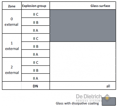
Fig. 7: Glass tube with and without dissipative coating
3.5.2.2. QVF® components made in dissipative PTFE
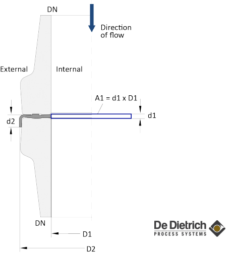
If components containing non-conductive plastics such as PTFE are used, their surface must not exceed a certain size. According to CLC/TR 50404 and TRGS727, the limit concerns the largest projected surfaces that are adjacent to explosive zones (see figures 10 and 11). These surfaces must not exceed the limits specified in table 5.
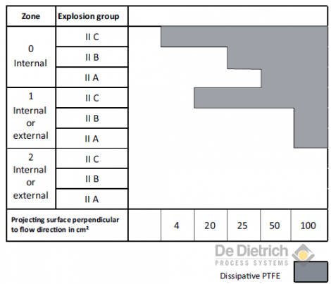
QVF® components made in PTFE such as gaskets, bellows, stirrers, bellows valves, etc. are available as dissipative versions. These components come with a certificate stating their dissipative properties and that their material properties conform to the relevant FDA regulations. For low to medium charge-generating processes, it is not always necessary that all PTFE components are made from a dissipative material (see also 3.5.2). Table 5 shows the maximum permissible non-conductive surface up to which the accumulation of dangerous charges is unlikely. According to TRGS727, the projected surface area of QVF® PTFE components is calculated separately for the inside and the outside of the component. Figure 10 shows the external projection surface of a PTFE gasket, while the internal projection surface is shown in figure 11. In zone 0, only the internal projection surface is taken into account when determining whether dissipative material needs to be used or not because the external surface area is not relevant for zone 0 as QVF® devices that are subject to ATEX 114 are not certified for zone 0 outside the QVF® glass plant. For zones 1 and 2, the larger of the two surfaces is taken into account. The values in table 5 can easily be converted into the diagram shown in figure 8. The selection diagrams below show whether dissipative PTFE is required or not, as a function of the nominal size of the component and the ATEX zone and explosion group adjacent to it.
Table 5: Limit surfaces for non-conductive materials according to CLC/TR 50404 4.4.3 table 1a
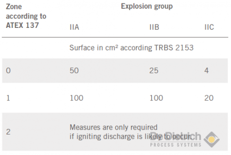
Fig. 8: Selection diagram for dissipative PTFE
Dissipative QVF® components do not feature any non-conductive surfaces and are included into the potential equalization system together with the conductive components. In contrast to standard components equipped with non-conductive PTFE, the metal parts of QVF® components that are equipped with dissipative PTFE, such as bellows, spacer plates, etc., might become electrically charged even if there are no electrostatic influence effects, and must therefore be included in the potential equalization system.
The main components that might be affected in this way are described in more detail below. If you require information on other QVF® PTFE components, please do not hesitate to contact us.
Fig. 9: Universal gasket of QVF® SUPRA-Line made in
PTFE, for all flange types
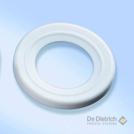
Fig. 12: QVF® SUPRA-Line flange types
.
.
Fig. 10: A2 = external projected surface
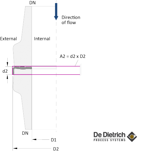
Fig. 11: A1 = internal projected surface
3.5.2.2.1. Gaskets – 9GG – 9GR
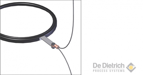
The universal gasket (item 4 in figure 5, and in figure 9) of the QVF® SUPRA-Line can be used in both "ball and socket" flanges and "flat" flanges (figure 12). The selection diagram (figure 13) shows that dissipative material is only required for gaskets of DN300 and larger. For the classification in zones 1 and 2, always the larger of the two projected surfaces (internal/external) is taken into account. The dissipative PTFE gaskets are equipped with a tab for the connection to the potential equalization cable (figure 14).
Fig. 13: Selection diagram for PTFE gaskets
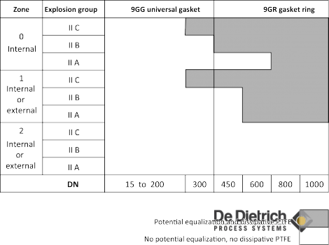
Fig. 14: Universal gasket made in dissipative PTFE with tab
3.5.2.2.2. Angular gaskets – 9GA
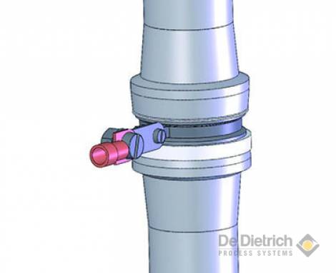
Angular gaskets (figure 16) allow for an angled orientation of QVF® SUPRA flat flange connections with minimum dead space. They consist of a PTFE sleeve supported by three stainless steel rings. The selection diagram in figure 15 shows that angular gaskets up to DN40 only require potential equalization in zone 1 IIC and zone 0 (internal). Angular gaskets of DN50 and larger, however, always require potential equalization. This is normally done with a metal tab attached to the centre stainless steel ring. The diagram also shows that angular gaskets of size DN40 and larger should be made in dissipative materialA in zone 0 IIC (internal).
Fig. 15: Selection diagram for angular gaskets
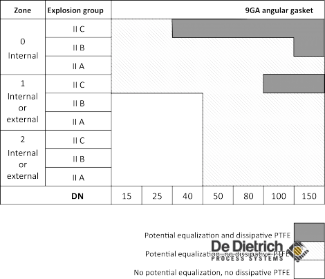
Fig. 16: Angular gasket made in dissipative PTFE with metal tab
3.5.2.2.3. Bellows – 9BW
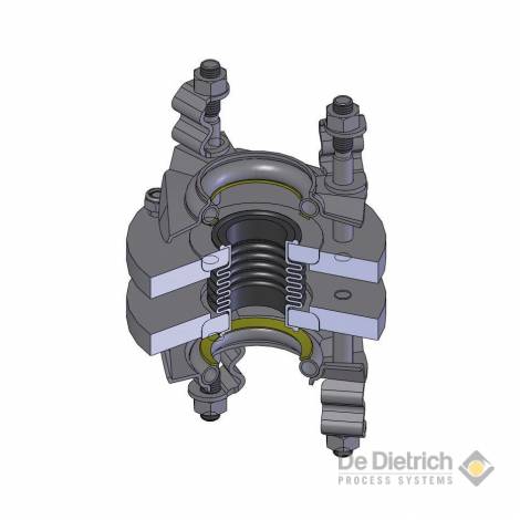
Bellows (figure 18) compensate for thermal expansion and contraction of the components due to thermal dilatation, and thus eliminate tensile stress in the glass components. The QVF® bellows are made in PTFE and are connected to the pipes by means of stainless steel flanges. As the projected surfaces perpendicular to the direction of flow are significantly larger than in gaskets, even relatively small bellows should be equipped with dissipative PTFE (figure 17). The diagram in figure 17 also applies to bellows with vacuum support. The bellows are conductively connected to a metal flange, which in turn has through the screws a conductive connection to the stainless steel flange ring of the QVF® SUPRA coupling. Potential equalization is implemented in the same manner as for stainless steel flange connections, by means of a continuous stainless steel cable clamped into the groove of the flange ring with a spring mechanism.
Fig. 17: Selection diagram for bellows
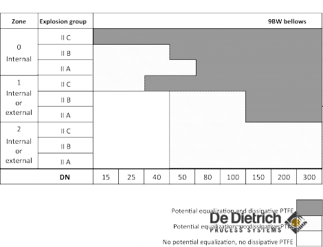
Fig. 18: Sectional drawing of bellows
3.5.2.2.4. Bellows valves – 3VO, 3VD, 3VV
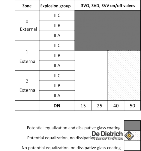
The QVF® SUPRA-Line bellows valves (figures 19 and 20) are used as stop valves or for coarse flow regulation. The top section of the valve is made in stainless steel and electrically connected to the PTFE bellows through a non-ferrous metal free spindle. The top sections of the bellows valves of DN40 are identical with those of DN50. Depending on the zone outside the plant, valves with a nominal size of DN40 therefore might also need to be equipped with potential equalization (see figure 22). The potential equalization cable is connected to the top section of the valve. The stainless steel cable is thereby clamped to the valve section that is also connected to the stainless steel flange rings. In valves with flange-mounted top section (figure 19), the stainless steel cable is attached in the same manner as in QVF® SUPRA flange connections. In valves with a compact top section, the cable is attached by means of a screw (figure 20). The zone outside the plant determines whether the glass housing of the valves needs to be equipped with a dissipative coating (see figure 22). By far the biggest part of the bellows is encased in the glass housing so that it can only be charged as a result of friction electricity inside the valve. The zone outside the plant is therefore irrelevant for determining whether dissipative PTFE is to be used for the valve bellows or not. Figure 21 shows the requirement for dissipative PTFE based on the zone inside the plant.
Fig. 19: Bellows valve with flange-mounted top section
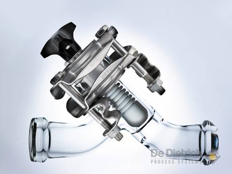
Fig. 20: Standard bellows valve with potential equalization connection
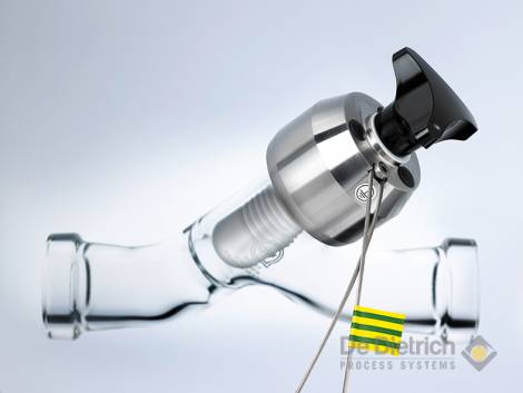
Fig. 21: Selection diagram for PTFE bellows of bellows valves
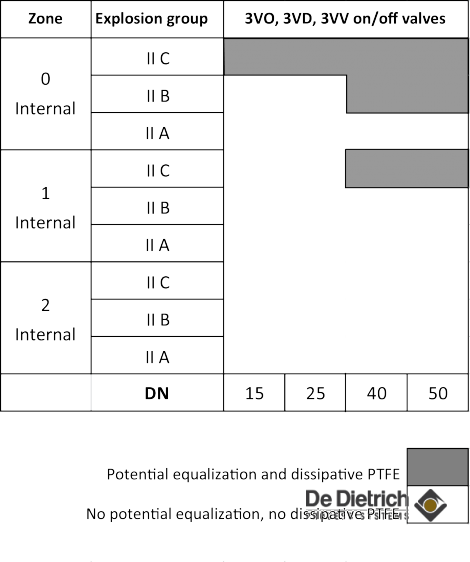
Fig. 22: Selection diagram for glass coating of bellows valves
4. Your Advantages with QVF® glass plants
Electrically, electrostatically and mechanically generated sparks can be avoided in QVF® plants made in borosilicate glass 3.3 according to ATEX directives and CENELEC code of practice. The corrosion-proof QVF® plants can thus be installed and operated safely in hazardous zones in accordance with the relevant operational safety regulations. This also applies where the inside of the plant is classified in zone 0.
The QVF® SUPRA-Line system provides you with safe solutions to avoid any possible electrostatic charges by:
• reliable, easy to install potential equalization of all flange connections
• patented dissipative glass coating
• dissipative PTFE components complying with FDA 21CFR §177&178
• ATEX-certified devices
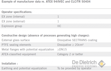
• reliable manufacturer data as regards compliance with CLC/TR 50404, as the example shown in table 6.
Table 6:
As a competent partner for advanced process systems, we would be delighted to assist you in finding the best solution for the safe implementation and proper documentation of your processes.
QVF® glass plants for all EX zones
